File:RLC_series.png · Wikimedia Commons · See Wikimedia Commons
RLC circuit
Sign in to saveAlso known as resistor inductor capacitor circuit
electrical circuit consisting of a resistor, an inductor and a capacitor, connected in series or in parallel
In the Vinony graph
Within Vinony's link graph, RLC circuit is referenced by 97 other articles, and connects out to damping, Laplace transform and pole.
It is catalogued under topics including Analog circuits and Electronic filter topology.
Its subject is documented across 35 Wikipedia language editions.
Wikidata facts
- Subclass of
- electronic circuit
- Has part
- inductor
- Image
- Parallel circuit(RLC).gif
Show 1 more fact
- Commons category
- LCR circuits
Sources (3)
via Wikidata · CC0
~39 min read
Encyclopedic overview
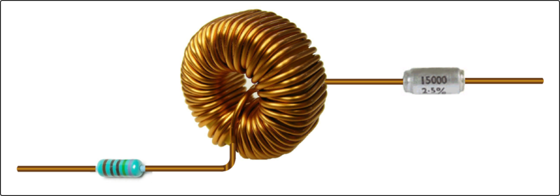
A series RLC network (in order): a resistor, an inductor, and a capacitor Tuned circuit of a shortwave radio transmitter. This circuit does not have a discrete resistor, but all circuits have some intrinsic resistance, causing them to function as an RLC circuit.
An RLC circuit is an electrical circuit consisting of a resistor (R), an inductor (L), and a capacitor (C), connected in series or in parallel. The name of the circuit is derived from the letters that are used to denote the constituent components of this circuit, where the sequence of the components may vary from RLC.
Excerpted from Wikipedia’s “RLC circuit” article, available under the CC BY-SA 4.0 licence.